Underwater 100 micro hydro generator
Submerged generator for fast flow zero head streams
The UW100 is a submerged generator designed for charging 12/24-volt battery systems from fast flowing zero head streams. Strictly speaking it is a picohydro generator ideally suited to difficult situations such as:
- Work Boat
- Seismic Survey Vessel
- Catamaran
- Navigation Buoy
- Water Supply Monitoring
- Remote Homes
- Aquaculture
Previously known as the Aquair UW (which created a lot of confusion with the Aquair) this outstanding submerged in-water generator is equally suited for use at sea or in fast flowing rivers, mountain streams & water pipe systems. It can be used in locations where bank layouts dictate that it is impossible to dam a flow to create a head, or where the water is flowing under ice, or in high speed towed applications such as streamers and racing catamarans. The cult status of the UW100 is because it offers the opportunity to generate up to 2.4kWh per day from any 400mm deep (15") fast flowing stream. When the stream flows at 8-knots (7mph; 15kph) the UW100 will produce 8 amps continuously, and when the stream flows at 6-knots (5mph; 10kph) it will still produce 1.5kWh per day. And remember that a stream can be diverted into a narrow culvert to increase flow rates.
- Starts charging at flows below 1m/sec (2 knots) - generates up to 8amps at 12v.
- Proven to depth of 10m.
- All water joints (mechanical & electrical) are double sealed.
- The oil filled housing has a pressure expansion chamber to allow operation at intermediary depths & in all temperatures.
 UW 100 technical description UW 100 technical description
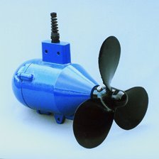
The UW 100 is a submerged water powered generator for 12/24 volt battery charging. It is a self-contained unit, (on-shaft propeller, streamlined housing, sealed alternator with pressure relief chamber), operating to depths of 10m below the water surface. The UW 100 features low waterspread cut-in (1½ knots) and a high charge rate (8 Amps) without sacrificing space for weight. The body is filled with hydraulic fluid to eliminate corrosion and to equalise temperature-induced pressure changes.
The forward facing 3 bladed propeller drives a permanent magnet alternator producing up to 8 Amps output current for a 12 volt system. The shaft rotates in double seals for optimum protection, backed by twin O-ring static seals at the rear of the casing. The cable exit is similarly double sealed by an internal moulding and external gland. The alternator body is filled with hydraulic fluid to eliminate corrosion and to equalise pressure changes caused by ambient temperature.
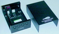
UW100 electrical information
Four metres of 4-core cable connects to two external rectifiers fixed on a heatsink which should be mounted in a suitable dry location near the battery. The output control switch and fuse are wired in the DC battery line. Any connector in the AC cable needs 4 individual contacts.
Propellor options
There a variety of different propellors available in production with the following three menu choices:
- Shrouded or unshrouded
Shrouded propellors should be slected whenever the water may contain rope or fishing line fragments, fine weed, or plastic debris.
- Clockwise or anti-clockwise rotation
Normal propellors rotate clockwise. The anti-clockwise version is to balance towed buoys with twin underslung units.
- Standard pitch or coarse pitch
Standard propellors are ideal for low speed start-up (1.8-knots) and thereafter produce approximately 1-amp per knot. Above 8-knots (4 metres/second) the coarse pitch (low RPM) propellor should be selected. This also reduces propellor drag at low speeds which is useful for racing yachts.
 |
 |
 |
 |
|
Standard, clockwise, unshrouded
|
Coarse, clockwise, unshrouded
|
Standard, clockwise, shrouded
|
Standard, anti-clockwise, unshrouded
|
Mounting systems
 The UW100 should be suspended in the flow by whatever means is available. Most clients choose to locally fabricate mounts but Ampair supply a variety of accessories to enable quick and reliable installation: The UW100 should be suspended in the flow by whatever means is available. Most clients choose to locally fabricate mounts but Ampair supply a variety of accessories to enable quick and reliable installation:
- Propellor guard
Stainless steel basket to screen out and deflect medium sized debris. Will not survive impacts from large boulders or tree trunks. Fits neatly over UW mounting pole.
- Mounting pole
Powder coated aluminium alloy pole with cast base holds UW100 firmly, protects cable and glands, and integrates with the propellor guard. Availble in 1.0 metre and 1.5 metre heights.
- Mounting clamps
Pair of aluminium alloy clamps to match pole. Not suited for salt water environments.
Dimensions

Charge control regulators for UW100
AMPAIR manufactures three 100 watt power Charge Control Regulators in 12-volt or 24-volt options for protecting lead acid batteries from overcharge They are not "shunt" type regulators, which dissipate excess charge as heat, but an electronic power switch which disconnects the generator from the battery at the regulation voltage.
Choosing an Ampair 100W charge control regulators
| Model |
Voltage |
Number of inputs
(Aquair, Ampair, or solar) |
Number of outputs
(battery banks) |
| S-1B-12 |
12 volt |
One |
One |
| S-1B-24 |
24 volt |
One |
One |
| S-3B-12 |
12 volt |
One |
Three |
| S-3B-24 |
24 volt |
One |
Three |
| D-1B-12 |
12 volt |
Two |
One |
| D-1B-24 |
24 volt |
Two |
One |
| Regulators S-lB & S-3B have a single 100 watt input (Ampair, Aquair or Solar) and 2 level sensing. Regulator type S-M1B has one output battery connection asnd regulator S-M3B has three output connections to serve up to three battery banks. The third Regulator D-M1B has two 100Watt inputs (any two from Ampair, Aquair or Solar), supplying a single battery bank at a fixed regulation voltage. |
 |
Advanced operation of Ampair charge control regulators
| Ampair charge control regulators continuously monitor the battery voltage. The lower voltage (Lo) connection regulates at 0 4 Volts below the high (Hi) connection, "Hi" connection is appropriate for liquid electrolyte batteries and/or live aboard situations. "Lo" connection for gel batteries and/or infrequent use. The battery voltage is sensed at the regulator output connection therefore install the regulator as near the battery as practicable and keep the connecting cables short. All regulators feature the same multi-stage regulation programme which has regulation voltages of Lo = 13.6v Hi = 14.0v. for 12V systems (27.2V & 28V for 24V systems). Charging is continuous until the Lo or Hi voltage is reached, depending on the battery output used. The generator is now disconnected from the battery. Off-charge, the battery voltage will fall. At a voltage of 0.5V below the regulation voltage a 30 second time delay is activated. This delay prevents the regulator from oscillation (hunting) when charging batteries under load. |
 |
| After 30 seconds has elapsed the generator/battery connection is remade and charging continues to the regulation cut-out voltage. A cycle counter counts the charge/disconnect cycles and at the tenth cycle increases the regulation voltage for one cycle only by 0.4 volt to Lo = 14.0v or Hi = 14.4v for 12 volt systems (0.8V for 24V systems Lo = 28.0V, Hi = 28.8V). This provides an equalisation charge for the battery. Subsequent cycles return to the lower settings until a further 9 cycles are completed. |
Ammeter: We recommend fitting an ammeter (see our price list) to monitor charging.
Fuses: Battery protection fuses should be fitted. Use 10 Amp values in 12 volt systems, 5 Amp for 24 volts
UW 100 further information
Exploded isometric parts drawing

Recommended short term spares
Recommended long term spares
Detailed performance curves
|
