

Technical Documents
Three-phase power solutions
We at Boost Energy discussed the options available to those who wish to power three-phase machinery.
Many readers will be familiar with the issue: they have either acquired or are considering acquiring a piece of three phase machinery yet they do not have three-phase electrical power in their premises. The purpose of this article is to outline the options available to them and
the factors they ought to take into account. It is not intended as a technical electrical engineering article but some basic electrical terms are introduced so that the article makes sense. The author is an engineer with the phase converter manufacturer Boost Energy Systems, but
the article attempts to present all the options objectively.
Why is three-phase machinery attractive?
Three-phase machinery is typically cheaper than single-phase machinery of the same power rating as it can be more easily located on the used machinery market. The reason for this is that historically single phase machinery has only been of low power, a situation which
is unlikely to change as most industrial machinery continues to be manufactured using three-phase motors. Single-phase motors of less than 1hp or so are readily available whereas motors of greater than 3hp are seldom single phase. Moreover, the poor starting torque characteristics of single-phase motors and their increased cost are such that if a machine has a primary three-phase motor in it – and
therefore can be assured of having three phase power available - then it is quite likely that the designers of the machine will have installed three-phase motors in even the smallest drives.
What is three-phase power?
Electricity comes in the form of either alternating current (A/C) or direct current (D/C). With direct current two wires are maintained with a steady potential difference between them, measured in Volts (V), and when a load is connected between the two wires current (measured in Amperes) flows from one to the other, doing work. The symbol for D/C is a straight line above a straight dashed line, which represents the fact that the voltage remains fairly constant in a D/C system.
The system of wires and loads is colloquially known as a network. However, for the vast majority of systems consuming significant amounts of power, electrical networks make use of alternating current for generation, transmission and distribution because with A/C transformers can be used to obtain different voltages. With a pure sinusoidal A/C wave form the voltage that is generally discussed is the root mean square (RMS) voltage because this is equivalent to the D/C voltage that produces the same heating effect for a given current. So, 240V RMS is equivalent to 339V peak, or 679V peak-to-peak and can be written as 240Vrms (the formula is Vrms = Vmax ÷ Ã2). Broadly speaking, current is related to voltage and resistance by the formula:
Voltage = Current (in Amperes) x Resistance (in ohms)
This is usually abbreviated to V = I x R.
So, in a given system, as voltage rises and falls so will current, although there can be a time lag between the two as a result of phenomena called ‘capacitance’ and ‘inductance’ in the circuit. In a three-phase network there are three live wires called L1, L2, and L3 and a potential
difference exists between each of these and neutral. If a potential difference of 240Vrms exists between each phase and neutral, if the phases oscillate at the same frequency, and if the frequency of each phase is offset by a constant and equal amount from each of the other two phases then the wave form is as shown in fig 1.
This diagram can also be drawn as a vector except that now each of the three phases occurs at 0, 120, and 240deg. around the neutral. The magic thing is that there is also a potential difference between L1 and L2, and L1 and L3, and L2 and L3. Simple maths reveals that the voltage between phases is 415Vrms and that this voltage also varies as a sinusoid (the formula is 240V = 415V ÷ Ã3). This is the system which we have in the UK, and it happens to operate at 50Hz, whereas most North American systems operate at 60Hz. This is how electrical distribution systems are set up so that three-phase 415V phase-to-phase is provided to industrial customers while domestic customers are provided with single-phase (neutral-to-live) 240V from the same network.

What are the options?
When considering the purchase of an item of three-phase machinery where only single-phase power is available there are five options:
- 1: Have three-phase power installed.
- 2: Move to somewhere with three-phase power.
- 3: Change the motors, etc. to single-phase.
- 4: Install a variable speed drive (VSD/VFD).
- 5: Install a single to three-phase converter.
I will now deal with each of the above options in turn.
Install three-phase.
In many parts of the world three-phase power is installed everywhere, however for various economic reasons and because of industrial history, this is not the case in the UK and some other countries including the Republic of Ireland, New Zealand, Australia, and the United States. Nevertheless it is always worth making contact with your local electricity company to ask whether a three-phase supply can be brought to your premises, and at what price.
Move premises
Quite frequently, small businesses unware of the existence of phase converters are driven to move premises in order to get three-phase power. This is unlikely to be an option for most readers in ‘domestic’ premises.
Change the motors
In fairly simple machinery it is possible to change a three-phase 415V motor for a single-phase 240V motor. The single-phase motor will
be bulkier, which can cause problems if the motor is embedded in a constrained space. Also, a single-phase motor might have insufficient starting torque; this might not be a problem for most machine tools, but is a real issue for loads such as car hoists and lifts in which the motor must develop maximum torque from rest. It is also necessary to check the coil voltages inside machinery. All in all it is seldom
cost-effective to change components in complex machinery, but it might be a sensible option in simple, easily accessed machinery.
Install a VSD
Variable speed motor drives (also known as inverter drives or variable frequency drives — VSD or VFD) work by taking the constant frequency sinusoidal A/C input, rectifying it to D/C, and then chopping it into a variable frequency A/C output with a fairly ‘blocky’ wave form. By altering the frequency of the wave form these are able to control the speed of the motor and by altering the nominal amplitude (i.e. the voltage) they are able to control the power available. A positive aspect of motor drives is that they provide considerable control over the operation of a motor – one can control the frequency (which determines motor speed) over a wide and continuous range, reverse
rotation, accelerate motors gradually from or to rest, and jog motors backwards and forwards.
However, all is not perfection, and motor drives do have limitations. First, because of the non-sinusoidal nature of the wave form, they should only be used to control motors. Secondly, they should only control one motor at a time, as otherwise all the motors will change speed in lock-step with the main motor. Thirdly, although a motor drive might be able to turn a motor at low speed this can cause the motor to burn out, as the cooling fan in the motor is shaft mounted and becomes ineffective at low speeds. From a technical perspective there are issues regarding the energy efficiency of motor drives (this is why they have such large heat sinks), but these are unlikely to trouble most readers.
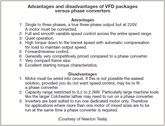
Because of these drawbacks it is typically necessary to rewire the machine tool to take a motor drive. If one enjoys rewiring machine tools this can be quite good fun, but one does need to keep an eye n the cost of it all. An alternative is to buy in a commercial VFD modification kit to suit your machine tool such as is shown in one of the photographs. A company called Newton Tesla is a regular advertiser in M.E. and M.E.W. and has standard packages built around off-the-shelf motor drives to suit the most common machine tools.
Phase converters
The final option is to use a single to three-phase converter. The easiest of these to visualise is a single-phase electric motor driving a three-phase electric generator and such motor generators do indeed exist. However, this approach is uneconomic for almost all applications. Having discarded the conceptually simplest, we are now left with three other types of phase converter: static phase converters, rotary phase converters, and sine wave inverters. Sine wave inverters are exactly the same as motor drive inverters in that they first rectify to
give D/C, and then invert it back to A/C but on three different phases.
The difference is that they add extra circuitry and so are able to give out a clean sinusoidal wave form, and they maintain a constant frequency. These could reasonably be termed ‘electronic converters’ which unfortunately is a rather ambiguous term that also gets misused to market variable speed motor drives and static phase converters, as well as many other things. These are only really used in the USA. Static converters and rotary converters are variants of the same basic design which has been utilised for several decades. It is worth considering all of the problems which can occur with static converters and then discussing rotary converters and how they overcome the problems. First, there has to be a motor in the circuit. A static converter simply cannot produce three phases on its own and so it will only power two of the three phases used in equipment such as ovens (unless they have a huge three-phase fan in them). However, this point is unlikely to trouble most readers unless they are contemplating using
welders, wire erosion machines, or plasma cutters. Secondly, the capacitance in the circuit needs to be matched to the inductance in the circuit.Unfortunately, the amount of capacitance required will change as the load varies on a given machine, or as different machines are operated. This characteristic is most pronounced when the primary motor starts as it will draw up to six times the normal current for a very brief period and the capacitance must vary accordingly.
Because of this the ‘boost’ circuit was introduced which switches in a much larger capacitance at motor start (long ago our company was named after this circuit). This boost can either be manual or automatic. Thirdly, because of the way the main motor is effectively generating the third phase it will only generate about two thirds of its maximum torque.
Thus it might not reach its maximum speed (especially if it has had very little margin in the machine tool’s design). Fourthly the largest motor must always be started first; this is probably okay in simple lathes and milling machines where operators can choose to switch the suds pump on after the main drive, but certainly cannot be guaranteed in more complex machinery. Fifth, if the motor stalls then it will start to ‘two-phase’ and will burn out its windings more readily than if it had been on a regular three-phase supply. Because of the requirement for the operator to manually tune, accurate phase balancing is always doubtful and so there exists the potential for sensitive machinery to be damaged. Similarly because there is a lowest level of capacitance there is a minimum size of motor that can be run. The bad reputation for static converters burning out motors partly arises from this and partly because if motors are frequently stopping and starting only
two phases have to bear the load. Just at the time when the motor most needs three phases it has only two available. Thus motors operated with a static phase converter can easily overheat. This is most pronounced with modern motors as, unlike older motors, they are designed with very little margin in either their electrical or thermal characteristics.
After all this you may well be wondering why a phase converter manufacturer can remain in business for any length of time! Well, a rotary converter improves things dramatically and so most reputable manufacturers encourage clients to purchase a rotary rather than a static converter wherever reasonably possible. A rotary converter
simply adds a correctly sized motor to a static converter. The motor has no mechanical function whatsoever and is simply there as an electrical component to create the third phase irrespective of what is happening to the driven loads. From a packaging perspective, a motor is basically iron and copper, and a transformer is basically iron and copper, and there are designs on the market that wrap up the transformer inside specially wound motors, in which case they are called rotary transformers (this design is widespread in the USA). The alternative approach is to use standard components, in which case the motor is known as a pilot, donkey, slave, idler, or auxiliary motor and
it can either be housed within the phase converter cabinet or placed separately. From a technical perspective there is little to choose between using standard components versus manufacturing rotary because there is a lowest level of capacitance there is a minimum size of motor that can be run.
The bad reputation for static converters burning out motors partly arises from this and partly because if motors are frequently stopping and starting only two phases have to bear the load. Just at the time when the motor most needs three phases it has only
two available. Thus motors operated with a static phase converter can easily overheat. This is most pronounced with modern motors as, unlike older motors, they are designed with very little margin in either their electrical or thermal characteristics. After all this you may well be wondering why a phase converter manufacturer can remain in business for any length of time! Well, a rotary converter improves things dramatically and so most reputable manufacturers encourage clients to purchase a rotary rather than a static converter wherever reasonably possible.
A rotary converter simply adds a correctly sized motor to a static converter. The motor has no mechanical function
whatsoever and is simply there as an electrical component to create the third phase irrespective of what is happening to the driven loads. From a packaging perspective, a motor is basically iron and copper, and a transformer is basically iron and copper, and there are designs on the market that wrap up the transformer inside specially wound motors, in which case they are called rotary transformers (this design is widespread in the USA). The alternative approach is to use standard components, in which case the motor is known as a pilot, donkey, slave, idler, or auxiliary motor and it can either be housed within the phase converter cabinet or placed separately. From a technical
perspective there is little to choose between using standard components versus manufacturing rotary transformers (each design has slightly different characteristics, but other technical factors are more important) and so commercial factors sway manufacturers to one design or the other.
A rotary largely eliminates the need for fine tuning of the capacitance and so phase converter manufacturers can then guarantee a certain amount of phase balancing across a given operating range — indeed there might be no level switches at all in a rotary phase converter. A rotary completely eliminates the problem of having to start the largest load motor first (or the need to have a load motor at all), and similarly eliminates the possibility of load motors ever two-phasing. Provided a rotary phase converter of sufficiently good quality is purchased, it will give an output that is equal in quality to the utility company’s three-phase supply. There is an extra purchase cost associated with a rotary converter as the motor and its starter, etc. need to be provided and transported. Indeed, in general, transportation costs are significant for such a heavy and low volume item as a phase converter, which is why there is little competition from non-UK producers. A general point, which applies to almost all phase converters, is that the three phases are not symmetrically distributed around the neutral. This means that they have to be connected carefully to operate machinery correctly.
Only Boost does a phase converter with a symmetric neutral. A commonly asked question concerns the efficiency of a phase converter. Efficiency is a function of the useful power output, so when expressed as a percentage it can be highly misleading if the useful load is very small. Instead, it is more straightforward to discuss the parasitic power consumption of a phase converter. A typical 4kW rotary converter has a fairly constant 500W of parasitic losses (windage, bearing losses, iron losses, and copper losses). So, at full power while supplying a 4kW load, it is 89% efficient but as load falls off this efficiency figure worsens, e.g. 67% for a 1kW load. This is one reason why it is better not to buy too large a phase converter, as ideally one would prefer to keep parasitic losses to a minimum. A final issue with phase converters is their power rating.
Until a few years ago, manufacturers used to place a fairly arbitrary label on their converters in horsepower and then advise clients to buy a converter “two to three times the size of the largest motor or larger.” Well, such a vague piece of advice is not very useful. Even though some ambiguity will always arise from the necessary translation of a client’s mechanical needs into a manufacturer’s electrical rating, most (not all) phase converter manufacturers have now moved to a system where they label their converters clearly as to maximum and minimum useful power ratings (in both horsepower and kilowatts, and taking into account internal parasitic power losses) for typical single motor and multi-motor cyclical duty.
Provided this has been done correctly by the manufacturer there is generally not much point in buying a much larger phase converter than they advise, unless you are considering purchasing larger machine tools in the future. Equally, it is unwise to buy a smaller converter on the basis that you are just a ‘hobby’ user. The phase converter is typically most stressed at start-up, which is an unavoidable element of the duty cycle and because an over-stressed phase converter will in turn stress your machine tool and can cause its motor(s) to burn out.
Power availability and protective devices
Irrespective of how you get your power, there needs to be enough of it. Any piece of machinery has a normal operating full load current (FLC) at a given voltage and/or a full load power. So if say it is a 3hp (2.2kW) lathe it will draw 9.2 Amps at 240 Volts single phase when fully loaded and in steady state operation:
2200W ÷ 240 Vrms = I = 9.17A single phase
2200W ÷ 415 Vrms = I = 5.3A total at unity power factor and 100% efficiency
5.3A ÷ Ã3 = 3.06 Arms per phase which is what you should find on the motor tally plate. However, it will draw 50 Amps or so from the
single phase supply when it starts up. Exactly how much current it will draw and for how long depends on the inertia of the load; clearly with a heavy, large diameter work piece, a lathe with a clutch is an easier start than one without. It is possible to get quite technical about fuse board (‘consumer unit’) design and various sorts of load factors so as to achieve a given probability of not tripping out. However, in practice you simply need to think about the likely domestic situation at the times you are going to use your machinery, and make due allowance.
In most small workshops only one piece of equipment is in use at a time and we have observed that with one exception all the items of equipment tend to be similar in power consumption, which facilitates this sort of calculation.
The exception is welders and similar items, which tend to have about four or five times the power consumption of anything else in a given workshop. With welders and similar equipment it is very important to obtain the actual power (kW) consumption of the item as simply knowing the weld current can be highly misleading unless one is absolutely certain of weld voltage and duty factor. The power supply to your workshop will have fuses or circuit breakers (often called miniature circuit breakers — MCBs), which are rated in Amperes for a given Voltage. A circuit breaker is a resettable electro-mechanical switch that automatically trips if the current through it exceeds a preset threshold.
Since its core component is a bi-metallic strip, it can accept an over-current situation for a pre-determined length of time. Most modern domestic premises will have type ‘A’ or ‘B’ rated circuit breakers installed, which will trip quite rapidly in an over-current situation. However, machine tools are industrial items that will draw an over-current at start up for somewhat longer than the average hair dryer. For this reason a motor rated circuit breaker should be installed throughout the circuit that feeds the workshop. Ideally, this should be a ‘D’ rated breaker but a ‘C’ rated breaker might be acceptable. A similar situation exists with fuses. Your phase converter supplier will advise you as to which rating breaker to install as they know the time for which a given breaker will hold in, e.g. 63 Amp ‘D’. They should not be much more expensive than a domestic breaker.
Returning to the average hair drier for a moment; it has three components which each have an electrical role to play. The switch is used
to start or stop it in normal operation or, if it is failing in service, the plug is used to disconnect it from electrical power so that one can safely
take it apart. The fuse in the plug is there to prevent an excessive current flowing and thereby protect both the user and the hair dryer. A phase converter is just the same. It needs a switch that can be operated to start and stop it in normal operation and should be immediately adjacent to it.
In converters of up to 6kW or so it is reasonable for this to be an MCB, and from 8kW and above this should be a motor starter. In the smaller converters of 6kW or less the MCB also acts as the over-current device and in the larger converters the overload relay in the motor starter fulfils this function. Converters of 8kW or above should also have an isolator fitted to positively isolate the internal
circuits when any covers are open. However, this isolator is not a suitable device for use as a starter, it is essentially a switch that should
only be operated with no current flowing as it is simply there to securely de-energise a section of a circuit. All these components should
either be integrated into the converter by the manufacturer or added into the total cost of purchase when comparing the prices of the
different manufacturers.
Other electrical supply and design issues
There is a wide range of other issues which your manufacturer will be aware of and can advise on, and which are covered in greater depth and detail in my feature published in Model Engineers’ Workshop No. 101, October 2004. Customer support and installation
Simply put, there are three stages of customer support: pre-sale, at sale, and post sale. None of the phase converter manufacturers mentioned are set up to accept on-line ordering and you will therefore need to talk to them by telephone or write/email/fax them in order to make a purchase.
In Boost’s case we deliberately operate this policy because we want to ensure that customers purchase a product that will suit their needs as we have seen too many instances of clients innocently pre-selecting inappropriate products over the years. Once you have talked through your situation with a manufacturer they will be able to advise you on your options and then you will purchase. Following this you will need to be in contact with them to arrange receipt (these are not packages that should be left on a doorstep) and often clients make use of the phase converter manufacturer for telephone support during installation.
Lastly you might need in-service support if a failure occurs, or if you are considering purchasing new machine tools or even selling your workshop and want pricing advice. It follows from all of this that the quality of service matters greatly and so you should be evaluating who is easy to contact, the calibre of their marketing literature (which may indicate the calibre of their phase converter manual), the duration and terms of any guarantees, and in general the extent to which they genuinely support their products. Finally, it is worth mentioning that all products have a natural lifetime. In the case of inverter drives and phase converters this is likely to be of the order of 5-15 years before the first components start to fail, depending of course on usage.
Choosing a solution
The simple table below can be used as a guide to select the most appropriate electrical power solution for your circumstances; just answer
questions in numerical order until you locate a suggested solution.

Conclusion
This article has outlined the different electrical options available to anyone considering the purchase of three-phase machinery. It has briefly
explained what three-phase power is and why it is commonly used in three-phase machinery. It touches on why three-phase power is not always available from the electrical utilities and then takes the reader through inverter based motor drives, re-motoring, and the different sorts of phase converters. Within phase converters it explains the limitations of static phase converters and how these are overcome to a great extent by rotary phase converters. The general message is that re-motoring and/or installing an inverter drive might suit the simpler and/or single machine workshops, but that a phase converter will suit a wider range of machinery. If buying a phase converter it is almost always worth stretching to a rotary phase converter rather than a static one.
A more comprehensive article on the same topic appears in Model Engineers’ Workshop No. 101, October 2004.